Diameter Dispersing Disc HSD Mixer
ukuran dispersing disc, diameter disc HSD, rasio disc terhadap tangki, high speed disperser design, tip speed HSD, desain HSD Mixer.
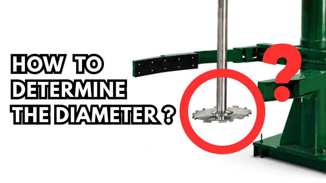
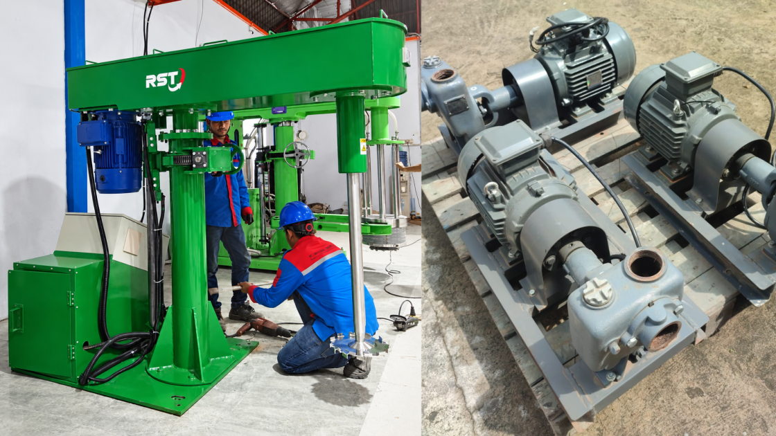
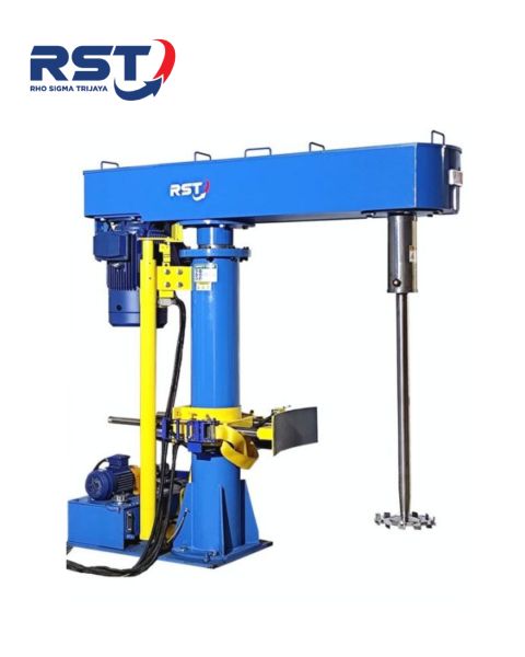
The dispersing disc diameter is one of the key design parameters in a High Speed Disperser (HSD Mixer). Disc size affects the linear velocity at the disc edge (tip speed), material flow patterns, powder wetting capability, and the mechanical load imposed on the motor and drive system.
In the manufacturing of paints, inks, coatings, adhesives, and chemical products, selecting the appropriate dispersing disc diameter helps achieve an effective and consistent dispersion process.
However, disc diameter should not be determined solely by motor power or tank capacity.
Engineering teams need to evaluate several parameters together, including tank internal diameter, working volume, material rheology, operating RPM, target tip speed, dispersing disc design, and process requirements.
This article explains an initial engineering approach to selecting the dispersing disc diameter for an HSD Mixer and the parameters that should be verified before finalizing the design.
1. What Is the Function of a Dispersing Disc in an HSD Mixer?
A dispersing disc is a circular component mounted at the end of a rotating shaft and immersed in the material. In conventional High Speed Dispersers, the disc typically features teeth around its outer edge.
As the disc rotates, it generates localized shear forces and material flow that help:
Wet powders during the addition process (powder wetting).
Break down pigment and particle agglomerates.
Circulate material through the disc working zone.
Improve dispersion uniformity throughout the batch.
Achieve the required product quality and formulation consistency.
The disc diameter influences these operating characteristics, but it is not the only factor determining dispersion quality.
Disc geometry, RPM, material rheology, tank configuration, disc positioning, and operating procedures also play important roles.
2. Disc Diameter to Tank Diameter Ratio
One of the initial geometric parameters used in HSD design is the ratio between the dispersing disc diameter and the tank internal diameter.
The formula is:
R = Dd / Dt
Where:
R = Disc-to-tank diameter ratio.
Dd = Dispersing disc diameter (mm).
Dt = Tank internal diameter (mm).
As an initial design approach, a disc-to-tank ratio of approximately 1:3 can be evaluated for many conventional HSD applications.
However, this ratio is not a universal standard. The actual ratio should be selected based on disc design and process characteristics.
Example: Calculating the Dispersing Disc Diameter
Assume the following design parameters:
Tank internal diameter = 900 mm.
Initial disc-to-tank ratio = 1:3.
The calculation is:
Dd = 900 / 3 = 300 mm
Therefore, an initial dispersing disc diameter of 300 mm can be evaluated.
This value is not automatically the final design dimension. It must be verified against operating RPM, tip speed, motor power, working volume, and material circulation requirements.
Initial Dispersing Disc Diameter Selection Table
The following table uses a 1:3 geometric ratio as an initial calculation reference.
| Tank Internal Diameter | Initial Disc Diameter |
|---|---|
| 300 mm | 100 mm |
| 450 mm | 150 mm |
| 600 mm | 200 mm |
| 750 mm | 250 mm |
| 900 mm | 300 mm |
| 1,000 mm | 333 mm |
| 1,200 mm | 400 mm |
| 1,500 mm | 500 mm |
Note: This table illustrates the geometric relationship between tank and disc diameters only. It is not a production capacity table or a final engineering recommendation for every application.
3. Should the Dispersing Disc Always Be One-Third of the Tank Diameter?
No. A 1:3 ratio should be treated as an initial design reference rather than a fixed requirement for every product or application.
Several factors can influence the selection of the actual ratio.
A. Material Rheology and Viscosity
Viscosity should be evaluated at the relevant operating temperature and measurement conditions.
For non-Newtonian materials, a single viscosity value may not adequately describe the material's behavior during mixing and dispersion.
Higher-viscosity materials can increase mixing loads and change material circulation patterns.
However, it is not correct to assume that every high-viscosity material requires a larger dispersing disc.
The selection must consider flow behavior, shear requirements, circulation capability, and the mechanical limitations of the machine.
B. Dispersion Process Requirements
If the primary objective is to break down pigment agglomerates, shear requirements and tip speed must be evaluated.
If the main objective is powder wetting and material circulation, the ability to move material through the disc working zone is also important.
C. Minimum and Maximum Working Volume
Tank diameter alone is not sufficient to determine the disc size.
Liquid height, minimum and maximum batch volumes, and disc immersion depth must also be evaluated.
A disc position that performs well at maximum tank capacity may not be optimal when operating with a smaller batch.
D. Motor Power and Mechanical Capability
A larger disc operating at the same RPM produces a higher tip speed.
Power requirements may also change and should be calculated or verified based on material characteristics and impeller design.
Any change in disc diameter must be evaluated together with motor capacity, torque, shaft, bearings, coupling, gearbox (if applicable), and lifting system.
4. Relationship Between Disc Diameter, RPM, and Tip Speed
Dispersing disc diameter must always be evaluated together with shaft rotational speed.
An important parameter is tip speed, which refers to the linear velocity at the outer edge of the disc.
The formula is:
v = (π × Dd × N) / 60
Where:
v = Tip speed (m/s).
Dd = Disc diameter (meters).
N = Shaft rotational speed (RPM).
Example: HSD Mixer Tip Speed Calculation
Assume:
Disc diameter = 300 mm = 0.3 m.
Shaft speed = 1,500 RPM.
The calculation is:
v = (π × 0.3 × 1,500) / 60
v ≈ 23.6 m/s
Therefore, the calculated tip speed under these operating conditions is approximately 23.6 m/s.
This is a calculated value, not a universal operating recommendation.
The appropriate tip speed must be determined based on product type, formulation, disc design, dispersion requirements, and process test results.
What Happens When the Disc Diameter Increases?
At the same RPM, increasing the disc diameter will increase tip speed.
This change may also increase power demand and mechanical loading, depending on operating conditions.
Conversely, a smaller disc produces a lower tip speed at the same RPM.
To achieve an equivalent tip speed, the RPM must be increased. However, increasing rotational speed is only acceptable if the motor, shaft, bearings, disc, and drive system are designed to withstand the required speed and mechanical loads.
Therefore, changing the disc diameter without evaluating RPM and power requirements can significantly affect HSD performance.
5. Dispersing Disc Position Inside the Tank
In addition to disc diameter, the disc position inside the tank also affects material circulation and dispersion performance.
Important parameters include:
Clearance between the bottom of the disc and the tank bottom.
Material depth above the disc.
Shaft position relative to the tank center.
Material level at minimum and maximum batch volumes.
Vortex depth during operation.
Potential air entrainment into the material.
Disc-to-bottom clearance and immersion depth should not be determined using one fixed value for every application.
These dimensions must be evaluated based on disc diameter, tank geometry, liquid level, disc design, and operating conditions.
Incorrect disc positioning may result in poor material circulation, low-flow zones, excessive vortex formation, or air entrapment in the product.
For HSD systems equipped with hydraulic lifting, the working position of the disc must be adjustable and safely secured according to operating requirements.
6. Effect of Tank Geometry on Disc Diameter Selection
Tank diameter is not the only geometric parameter that affects disperser performance.
Tank bottom design, liquid height, baffles, internal nozzles, and other internal components can influence material flow patterns.
Flat-Bottom Cylindrical Tank
This configuration is commonly used in various industrial applications.
Engineering evaluation should consider the possibility of low-circulation zones near the tank bottom and side walls.
Dished or Bowl-Shaped Tank
A curved tank bottom can help reduce areas where material accumulates in corners, depending on the bottom geometry and outlet design.
Tanks with Internal Components
Baffles, pipes, nozzles, coils, and other internal components can change material flow patterns.
Therefore, disc diameter and shaft positioning should be evaluated together with the complete tank configuration.
7. Common Mistakes in Selecting an HSD Dispersing Disc Diameter
Several common design mistakes should be avoided:
1. Treating the 1:3 ratio as an absolute rule.
This ratio is only an initial reference and must be verified for the actual application.
2. Selecting the largest disc that physically fits inside the tank.
A larger disc does not automatically produce better dispersion.
3. Ignoring tip speed calculations.
Disc diameter and RPM together determine the tip speed.
4. Ignoring minimum batch volume.
A disc position suitable for a full tank may not perform effectively at a smaller batch volume.
5. Failing to check mechanical limitations.
The shaft, bearings, coupling, and drive system must be suitable for the operating load and rotational speed.
6. Assuming disc diameter alone determines dispersion quality.
Formulation, powder wetting, processing time, temperature, disc geometry, and operating procedures also influence the final result.
8. Engineering Checklist Before Determining HSD Disc Diameter
Before finalizing the dispersing disc size, make sure the following information is available:
Tank internal diameter and tank height.
Minimum and maximum working volume.
Material height at each batch condition.
Product type and rheological characteristics.
Viscosity and operating temperature.
Specific gravity or material density.
Dispersion target and processing time.
Dispersing disc type and geometry.
Operating RPM range.
Target tip speed, if specified.
Motor capacity and torque requirements.
Shaft, bearing, coupling, and drive system specifications.
Disc-to-bottom clearance and immersion depth.
Potential vortex formation, air entrainment, and low-circulation zones.
Machine safety requirements and mechanical limitations.
If process information is incomplete, the disc diameter can be estimated as an initial design value.
However, the final dimensions should only be established after engineering evaluation and, where necessary, process testing.
9. FAQ: HSD Mixer Dispersing Disc Diameter
What is the recommended disc-to-tank diameter ratio for an HSD Mixer?
A ratio of approximately 1:3 can be used as an initial reference for many conventional HSD designs.
However, the final ratio may vary depending on disc type, tank geometry, material rheology, RPM, and process requirements.
How do you calculate the dispersing disc diameter?
As an initial estimate, divide the tank internal diameter by the selected ratio.
For example, a tank with an internal diameter of 900 mm and a 1:3 ratio gives an initial disc diameter of 300 mm.
Does a larger dispersing disc always provide better dispersion?
No. A larger disc can increase tip speed at the same RPM, but it may also increase power demand and mechanical loading.
Dispersion quality depends on the complete equipment design and process conditions.
What is the relationship between disc diameter and tip speed?
Tip speed is the linear velocity at the outer edge of the disc.
It depends on both disc diameter and shaft RPM. At a constant RPM, increasing disc diameter increases tip speed.
Does viscosity determine the dispersing disc diameter?
Viscosity is an important design parameter, but it should not be used alone.
Rheology, material density, working volume, dispersion targets, RPM, and power requirements must also be evaluated.
Can the disc diameter be determined only from tank capacity?
No.
Tank diameter can provide an initial geometric estimate, but liquid height, working volume, material characteristics, disc position, RPM, and process requirements must also be considered.
10. High Speed Disperser Design Consultation – PT Rho Sigma Trijaya
PT Rho Sigma Trijaya (RST) specializes in custom industrial mixing equipment and stainless steel tank manufacturing for the paint, ink, coating, adhesive, and chemical industries.
When designing a High Speed Disperser, RST Engineering evaluates the dispersing disc diameter together with other critical parameters, including tank diameter, batch volume, material characteristics, RPM, tip speed, motor capacity, and mechanical configuration.
If your company is planning a new HSD Mixer or evaluating an existing machine, our Engineering team can discuss your application requirements and available process data.
Contact PT Rho Sigma Trijaya to discuss your High Speed Disperser requirements.
Website: https://www.rhosigmatrijaya.co.id/
Email: sales1@rhosigmatrijaya.co.id
Contact the RST team to discuss dispersing disc dimensions, motor power, batch volume, and the appropriate HSD Mixer configuration for your application.